
Introduction
Following the trail, you arrive at a shining pond.
A green frog jumps onto a leaf and greets you:
“Welcome to the reflection pond!
Here everything works in reverse: if something is on, it turns off;
if it’s off, it turns on. This is NOT logic.”
Your mission is to build a circuit that inverts the input signal.

What is the NOT gate?
- It has one input and one output.
- The output is always the opposite of the input.
See full truth table
| Input A | NOT Output |
|---|---|
| 0 | 1 |
| 1 | 0 |
This gate is also called an inverter.

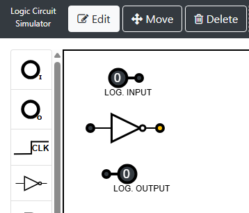
Simulator instructions
1. Place the components
- Make sure you are in Edit mode.
- In the left sidebar, select and place:
- Input ➔ one input (A).
- NOT Gate ➔ a NOT gate between the input and the output.
- Output ➔ an output to the right of the gate.
2. Connect the components
- Connect the output of Input A to the input of the NOT.
- Connect the output of the NOT to the Output.
3. Test the circuit
- Click on Input A to toggle
0↔1. - Watch the Output: it should show the opposite of A.
Victory condition:
- If
A = 0➔ Output = 1 - If
A = 1➔ Output = 0
The frog claps:
“Well done! Sometimes, to move forward you need to think in reverse.”
Quick tips
- If the output does not change to the opposite of the input, check that the wire goes through the NOT gate.
- Confirm that you selected NOT Gate and not another gate.
- If the output is the same as the input, the NOT gate is probably not connected or is missing.
Challenge (optional)
- Double NOT: add two NOT gates in series. What happens to the output?
Simulator
What did you learn?
- The NOT gate inverts the logical value:
0 → 1and1 → 0. - It is useful for creating inverse behaviors (alarm when signal is absent, automatic lights, etc.).
- Two NOT gates in a row cancel each other out.
Next up
Excellent! In the next activity, the Little Monkey will show you how to combine AND, OR, and NOT to solve more complex challenges and restore the energy to the Forest Sphere.