Activity 3 - Joystick + LEDs
Let’s combine activity 1 and activity 2. Let’s control LEDs based on the input from the joystick.
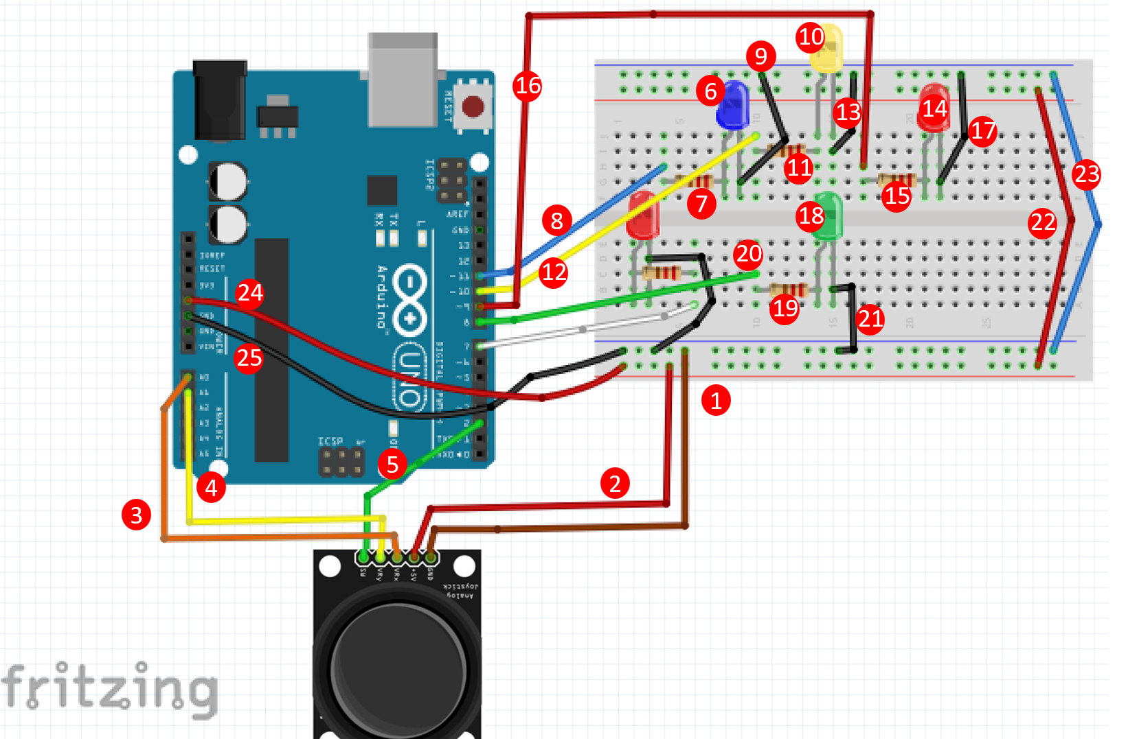
- Attach one end of a jumper wire to GND on the joystick and the other to 7X on the Breadboard.
- Attach one end of a jumper wire to +5V on the joystick and the other to 5W on the Breadboard.
- Attach one end of a jumper wire to VRx on the joystick and the other to A0 on the Elegoo.
- Attach one end of a jumper wire to VRy on the joystick and the other to GND on the Elegoo.
- Attach one end of a jumper wire to SW on the joystick and the other to 2 on the Elegoo.
- Attach the long lead (anode) of your blue LED to pin 8F and the short lead (cathode) into pin 9F.
- Attach a 220 resistor with one leg in 8G and the other in 4G.
- Attach one end of a jumper wire to 4H on the Breadboard and the other to 11 on the Elegoo.
- Attach one end of a jumper wire to 9G and the other to 12Z (anywhere in the blue [-] line) on the Breadboard.
- Attach the long lead (anode) of your yellow LED to pin 14J and the short lead (cathode) into pin 15J.
- Attach a 220 resistor with one leg in 14I and the other in 10I.
- Attach one end of a jumper wire to 10J on the Breadboard and the other to 10 on the Elegoo.
- Attach one end of a jumper wire to 15I and the other to 18Z (anywhere in the blue [-] line) on the Breadboard.
- Attach the long lead (anode) of your red LED to pin 21F and the short lead (cathode) into pin 22F.
- Attach a 220 resistor with one leg in 17G and the other in 21G.
- Attach one end of a jumper wire to 17H on the Breadboard and the other to 9 on the Elegoo.
- Attach one end of a jumper wire to 22G and the other to 25Z (anywhere in the blue [-] line) on the Breadboard.
- Attach the long lead (anode) of your green LED to pin 14A and the short lead (cathode) into pin 15A.
- Attach a 220 resistor with one leg in 10B and the other in 14B.
- Attach one end of a jumper wire to 10C on the Breadboard and the other to 8 on the Elegoo.
- Attach one end of a jumper wire to 15B and the other to 17X (anywhere in the blue [-] line) on the Breadboard.
- Connect the blue [-] rails together with a jumper wire
- Connect the red [+] rails together witha jumper wire
- Attach one end of a jumper wire to the +5V on the Elegoo and the other anywhere on one of the red [+] lines.
- Attach one end of a jumper wire to the GND on the Elegoo and the other anywhere on one of the blue [-] lines.
The Code
int button=2;
int buttonState=0;
int buttonState1=0;

void setup() {
  pinMode(7,OUTPUT);
  pinMode(button,INPUT);
  digitalWrite(button,HIGH);
  Serial.begin(9600);

  pinMode(8,OUTPUT);
  pinMode(9,OUTPUT);
  pinMode(10,OUTPUT);
  pinMode(11,OUTPUT);
}

void loop() {

 int xValue = analogRead(joyX);
 int yValue = analogRead(joyY);

  Serial.print(xValue);
  Serial.print("\t");
  Serial.println(yValue);
  buttonState = digitalRead(button);
  Serial.println(buttonState);

  if (xValue>=0 && yValue<=20)
  {
    digitalWrite(10,HIGH);
  }
  else{digitalWrite(10,LOW);}

  if (xValue<=20 && yValue>=490)
  {
    digitalWrite(11,HIGH);
  }
  else{digitalWrite(11,LOW);}

  if (xValue>=1010 && yValue>=490)
  {
    digitalWrite(9,HIGH);
  }
  else{digitalWrite(9,LOW);}

  if (xValue>=490 && yValue>=1010)
  {
    digitalWrite(8,HIGH);
  }
  else{digitalWrite(8,LOW);}

  if (xValue>=1010 && yValue>=1010)
  {
    digitalWrite(9,LOW);
    digitalWrite(8,LOW);
  }

  if (buttonState==LOW)
  {
    Serial.println("Switch = High");
    digitalWrite(7,HIGH);
  }
  else{digitalWrite(7,LOW);}
  buttonState1=digitalRead(7);
  Serial.println(buttonState1);
  delay(100);
}