Wiring the Joystick
Now that you understand how we can get the system to provide signals from the program (outputs) and use those to control LEDs, let’s look at how we can get dynamic inputs into the system. For this activity we will use a joystick input, similar to those used in video game consoles.
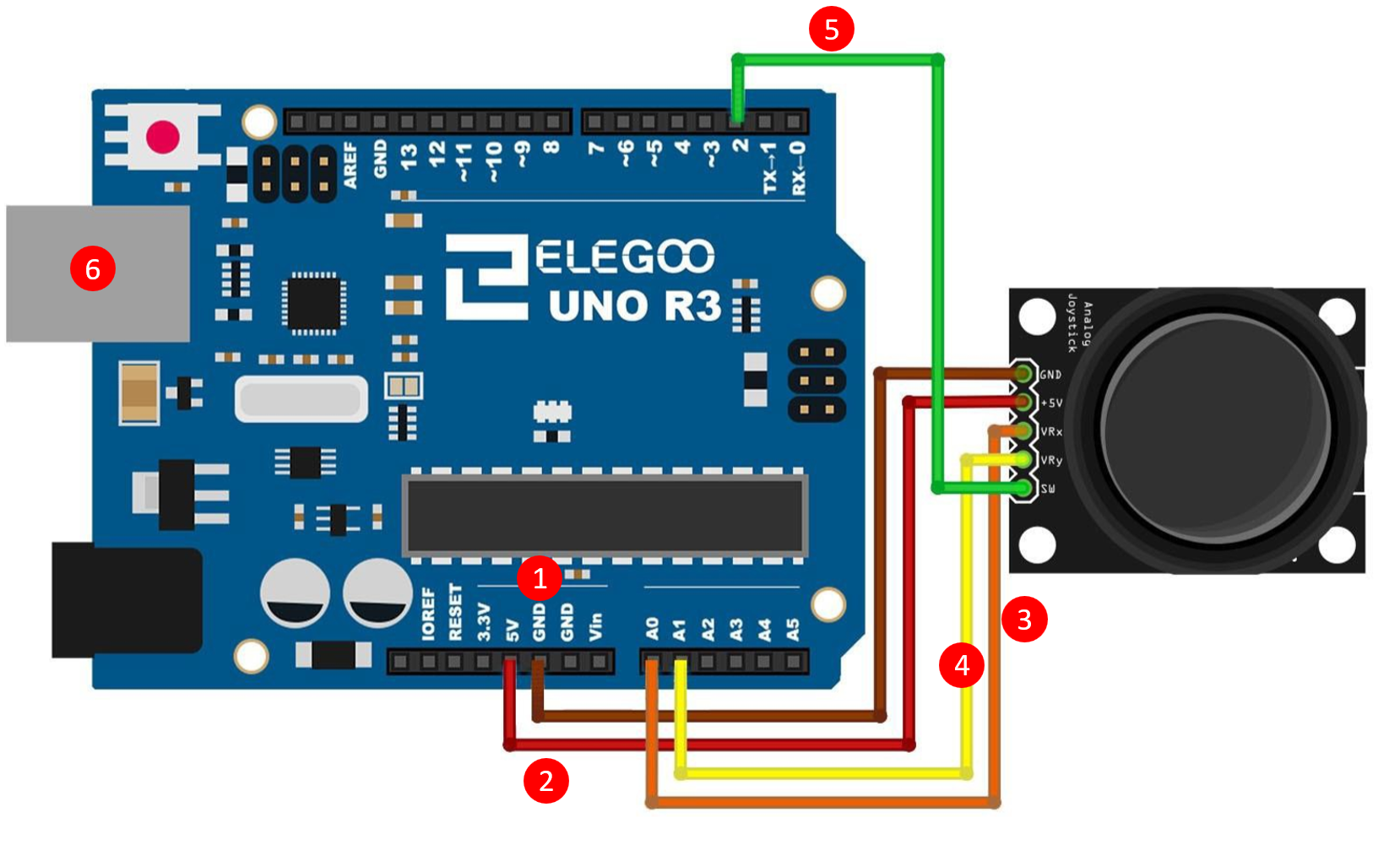
- Attach one end of a jumper wire to GND on the joystick and the other to GND on the Elegoo.
- Attach one end of a jumper wire to +5V on the joystick and the other to 5V on the Elegoo.
- Attach one end of a jumper wire to VRx on the joystick and the other to A0 (analog pin 0) on the Elegoo.
- Attach one end of a jumper wire to VRy on the joystick and the other to A1 (analog pin 1) on the Elegoo.
- Attach one end of a jumper wire to SW on the joystick and the other to 2 (digital pin 2) on the Elegoo.
- Plug in the Arduino board via USB to your PC and open the Arduino IDE application.
Recognizing and printing Analog Inputs
We will again use sample code for our programs. This time we’ll get it from the elegoo website itself. Copy the following into your Arduino IDE.
//www.elegoo.com
//2016.12.09

// Arduino pin numbers
const int SW_pin = 2; // digital pin connected to switch output
const int X_pin = A0; // analog pin connected to X output
const int Y_pin = A1; // analog pin connected to Y output

void setup() {
  pinMode(SW_pin, INPUT);
  digitalWrite(SW_pin, HIGH);
  Serial.begin(9600);
}

void loop() {
  Serial.print("Switch:  ");
  Serial.print(digitalRead(SW_pin));
  Serial.print("\n");
  Serial.print("X-axis: ");
  Serial.print(analogRead(X_pin));
  Serial.print("\n");
  Serial.print("Y-axis: ");
  Serial.println(analogRead(Y_pin));
  Serial.print("\n\n");
  delay(500);
}
- Now click the upload button to deploy the program to the Arduino.
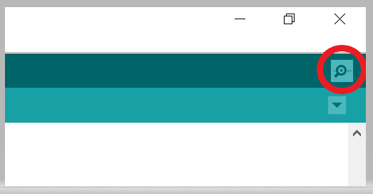
- Click on the “Serial Monitor” button on the top right of the screen to display the console.
- Notice how the X and Y values change when you move the joystick around.