Wiring Our Blinking LED
For your introduction to this system, we’re going to turn an LED on and OFF. From this we can get the basics of circuitry and how our program can run and manipulate components.
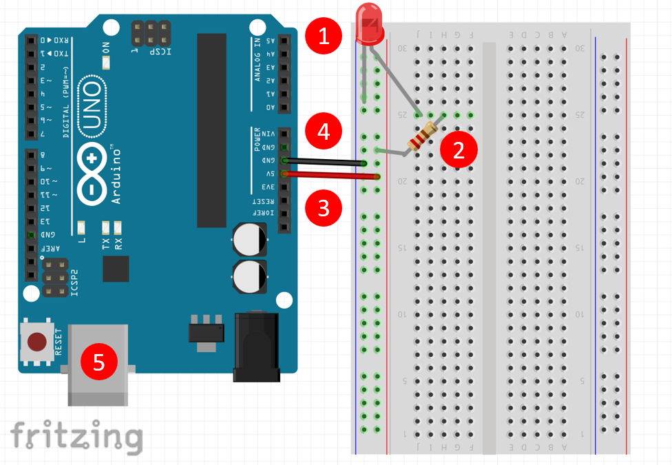
- Attach the long lead (anode) of your LED to pin 25J and the short lead (cathode) anywhere in the blue [-] line.
- Attach a 220 resistor with one leg in 25H and the other anywhere in the red [+] line.
- Attach one end of a jumper wire to anywhere in the same red [+] line on the Breadboard as Step 2 and the other to 5V on the Elegoo.
- Attach one end of a jumper wire to 31Z on the Breadboard and the other to GND (ground) on the Elegoo.
- Plug in the Arduino board via USB to your PC and open the Arduino IDE application.
Color-coding wires is common and really helpful! Here we used red for positive charge and black for negative charge but the color doesn’t matter so long as you can remember what is what.
Opening LED Sample Code
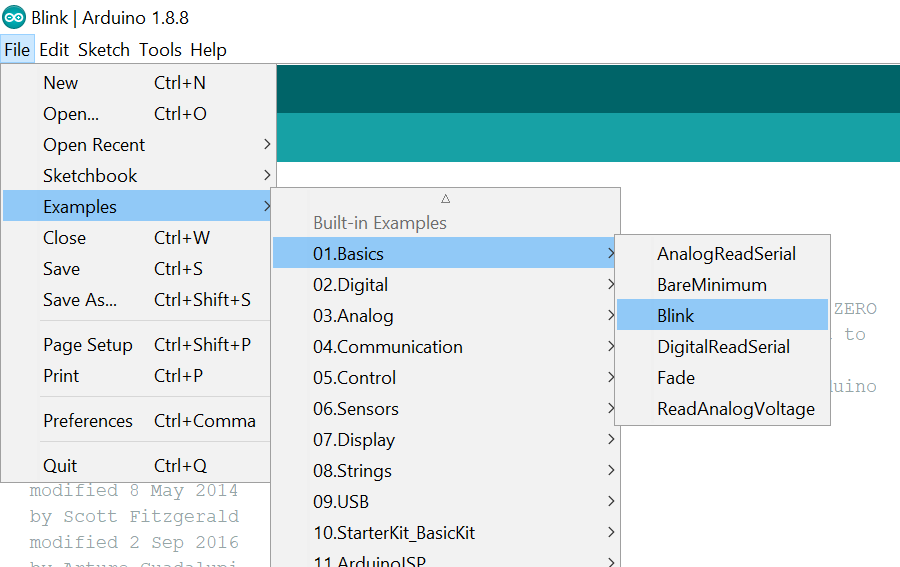
- Click on File -> Examples -> 01.Basics -> Blink
- Now click the upload button to deploy the program to the Arduino.
EXTRA: Notice the timing of the LED turning on and off. What do you think you could change in the program to modify that timing? If you said the number 1000 in delay (1000); you are RIGHT! Change that number (don’t forget to hit the upload button again). Notice a difference? Why do you think 1000 is 1 second? How long would 10 minutes be? Why?